
In many code examples there are delays with Loops used for timekeeping Events. This is a really bad idea, because the microcontroller runs full power without doing a Thing that is needed. For Battery powered Projects this cuts the lifetime of the battery enormous. By the way it is not good for the Environment.
WordPress seems to write some words big and some small randomly. So please do not wonder why some words are written wrong.
I want to Show how you can use a timer for timekeeping Events instead of delays. This Blog entry is made for Beginners like me, and if there are any questions, just ask in a comment.
We start with the code Composer Studio MSP Ware code examples selection. If you dont have the MSP ware installed it is no Problem. The code for this will follow below. But the MSP ware is really helpful, so let me Show.
At first you have to select the TI Resource Explorer if it not already visible after CCS Startup.

A good source for code examples.
Then you should select MPS430ware, Devices, MSP430G2xx.
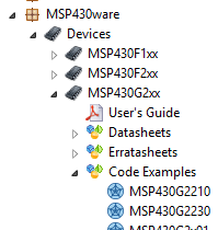
For the Launchpad you have to choose MSP430430G2xx in the Device Menu.
After selecting the right Microcontroller in the Code Examples Menu you see the available Examples on the right side.

The Examples are Available as „one Click Projects“, C Code and Assembler too.
This time we use a one click Project, a really helpful Thing.
The Example that i am going to explain is the „Timer_A, Toggle P1.0, CCR0 Cont. Mode ISR, DCO SMCLK“ Example. For this example you dont Need a breadboard or additional elements. Only the Launchpad equipped with a microcontroller of your choice.
After clicking on the Project you have to slect the Microcontroller you have put into your Launchpad. For me it is the MSP430G2553 at the Moment.

Select your used Microcontroller. If you use a 2231 you have to select it under Devices a step earlier on the left side under MSP430G2x31.
When this is done your Project should be selectable in the Project Explorer on the left side.
Se the code by double clicking on the c file.
As you can see the Code is well explained, and the code itself is short and easy. Let me explain it line by line. But at first the whole Code.
Original Texas Instruments sample code
#include<msp430.h>
int main(void){
WDTCTL = WDTPW + WDTHOLD; // Stop WDT
P1DIR |= 0x01; // P1.0 output
CCTL0 = CCIE; // CCR0 interrupt enabled
CCR0 = 50000;
TACTL = TASSEL_2 + MC_2; // SMCLK, contmode
_BIS_SR(LPM0_bits + GIE); // Enter LPM0 w/ interrupt
}
// Timer A0 interrupt service routine
#pragma vector=TIMER0_A0_VECTOR
__Interrupt void Timer_A (void){
P1OUT ^= 0x01; // Toggle P1.0
CCR0 += 50000; // Add Offset to CCR0
}
Maybe there are Things you already know, but i explain it for the one who does not know what it means.
#include<msp430.h>
That includes a file of definitions for the msp430 Family, where ports and Registers are named and what is really useful as a reference for you too. It is recommended to Change this to the Microcontroller you are using. For my example this would be „#include<msp430g2553.h>“.
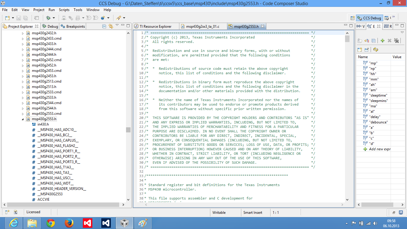
Let us look at the .h file we include.

Select the upper file from ccs_base, and click on the marker at the left to show the included files.
There you have to select the „msp430g2553.h“ file and double click on it to open the file. I use the MSP430G2553, so if you are using the 2452 for example please choose the „msp430g2452.h“ file. Every Microcontroller type has his own h file.
A lot to scroll here.
We will Need this file to explain the following steps.
int main(void){
this is the beginning of the main Loop of the Project that every c-program has.
WDTCTL = WDTPW + WDTHOLD; // Stop WDT
This Switches the Watchdog timer off. The Watchdog is a timer that controls the microcontroller. If your program causes the Microcontroller to hang up, it initializes a reset or something you told him to do. You might think „Hey, sounds important, why should we Switch that off?“. That was a Thing i also thought first, but Watchdog handling is not easy to understand and if you do it wrong it causes restarts and you dont know if it is an error in your code or a watchdog configuring mistake. So it is really recommended to turn it off as a beginner.
The lines Sound like a mysterious code, but most times it is much easier to read if you know what it means. WDTCTL might Sound horrible, but if you know it means WatchDogTimerConTroL it is like the clouds go away and the sun comes out. The line sets the Watchdog timer on Hold, what means off. It does that by Setting the WDTHOLD bit. But what is WDTPW? That is the Watchdog Timer Password bit. The watchdog is saved by Password protection to avoid unwanted Settings caused on programming mistakes.
P1DIR |= 0x01; // P1.0 Output
This sets the Port 1 Register to Output for Port 1.0. Most Things on the MSP are simply controlles by switching a bit to one or Zero. That is on other Systems the same, but here you can see how the Zeros and ones work. I like that most on the MSP430. It helps me understanding how Computers work. P1DIR is the direction Register for the port 1. The „|=“ means put it to one (Switch on). 0x01 means the first bit in hexadecimal what is port 1.0 in this case.
CCTL0 = CCIE; // CCR0 interrupt enabled
This sets the Capture/Compare control 0 to enable Timer Interrupts. CCIE means „Capture/Control Interrupt Enable“. All These bizarre names are defined in the .h file. Dont be afraid to check the .h file and read what it contains.
CCR0 = 50000;
This sets the Capture/Compare Register 0 value to 50000. This is the value to reach for firing the Interrupt. With this value you can control the time that must be over between each Interrupt Event of the CCR0 Interrupt handler.
TACTL = TASSEL_2 + MC_2; // SMCLK, contmode
Here we set the mode the Timer A uses. TACTL = Timer A ConTroL.
TASSEL_2 you can find in the .h File.
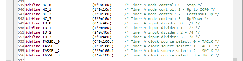
TASSEL_2 explained.
With TASSEL_2 we select the SMCLK what is the SubsystemMasterCLocK. There are some other Clocks available, but i dont explain this in Detail here.
MC_2 is Setting it to Continuous Up mode what means it Counts up to the highest value available for the microcontroller (I do not know a lot about that, i mostly use MC_1, what means up to CCR0.)
CCR0 is a Timer that clears ist Interrupt flag itself. That means if CCR0 (the value we set to 50000 before) is reached an Interrupt will be fired. At this Moment the code stops the normal execution and jumps to the Interrupt handler. If there where more than one Interrupt there is a priority that says what Interrupt will be handled first. If the Interrupt has fired there is a flag that Shows this (CCR0IFG where IFG means InterruptFlaG). CCR0 cleares this flag itself. All the other (CCR1 and so on) Need to put the flag down manually. That is important. If you dont put the flag down it the next Interrupt will not fire when reaching the Value.
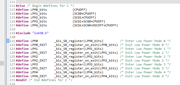
_BIS_SR(LPM0_bits + GIE); // Enter LPM0 w/ Interrupt
Enter the most powersaving sleepmode. This line is not easy to explain. It means that the Microcontroller sets the bits that are definded for LPM0 (LowPowerMode 0). That is the part LPM0_bits. And it also enable all Interrups (GIE = General Interrupt Enable).
It is also possible to Write LPM0, but then you have to set GIE too if you want that all Interrupts should work.
All These Low Power modes are defined in the .h file.
The Sleep mode works like this:
- Enter sleep mode.
- Interrupt starts
- code from Interrupt handler is executed
- back to sleep mode.
If you are using Sleep modes, you have to know that when sleep mode is called, the code will start after wakeup at the Position after sending to sleep. It is not like rebooting the System.
The defines are short Versions of the commands behind.
}
End of the Main Loop. If you want to execute code continuosly You have to put a While loop
// Timer A0 interrupt service routine
#pragma vector=TIMER0_A0_VECTOR
__Interrupt void Timer_A (void){
This is the beginning of the Timer 0 Interrupt handler. This code is executet when the Interrupt is fired by the timer. I do not now what that #pragma and the vector names exactly mean. So i can not explain this. But in the different timer examples the vectors are named, and i use These names without modifying.
P1OUT ^= 0x01; // Toggle P1.0
In this example the Interrupt toggles the port 1.0 when fired. Toggle means a one will turn to Zero, and a Zero to one. Perfect for blinking LEDs. „^=“ means toggle.
CCR0 += 50000; // Add Offset to CCR0
This adds a value of 50000 to the CCR0 value, so the Interrupt will be fired after further 50000 ticks of the clock. If you use MD_1 (up mode to CCR0) you would not Need this, because CCR0 would set to Zero after reaching the given value. If you would not add a value in continuos upmode it would fire after reaching 50000 again with TAR what is the current timer value.
Adding values for the next Interrupt step could be tricky when you are using more timers. If you set CCR1 (The Interrupt value for Timer A1) to a higher value than CCR0 it will never fire an Interrupt, because CCR0 is the „master“ timer. I ask myself at the Moment why the adding in this example does not cause an error when the value reaches a higher value than the microcontroller could handle. But this i will find out later.
}
End of the Interrupt handler.
Unanswered questions?
If there are unanswered questions please ask, if i am wrong with my thoughts please tell it to me. sometimes i put more Information than needed to the lines of code, but i think it is important to know some things related to the Special functions.

Kommentar verfassen